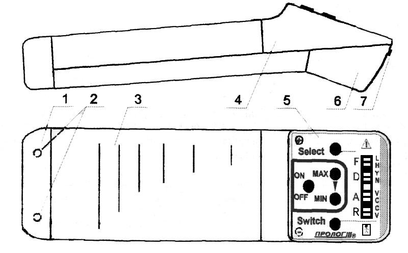
The main electrodes (1) are located at one side of the apparatus (3). On the opposite side are located: the frame (4) with control and indication panel (5), the cover (6) with the button (7) for opening the battery compartment in which the battery is installed.
During operation with detachable electrodes, the latter should be connected in parallel to the main electrodes via sockets (2), located on the main electrode carriers (1).

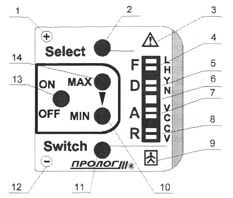
Warning (3) that before switching on the apparatus, the user should read these instructions.
Warning (9) that the apparatus belongs to
class BF and as such
is not designed for direct application to the heart.

The on/off button (13) "
ON-OFF."
Buttons (14 and 10), "
MAX" (maximum), "
MIN" (minimum), which determine the intensity value.
The button (11) "
SWITCH," which changes the operating mode.
The button (2) "
SELECT," which allows a group of modes to be selected.
LCD mode indicators:
1. Group "
F" (Frequency) indicators (4): "
L" (Low), "
H" (High), "
L" and "
H" (medium), which set the operating frequency;
2. Group "
D" (Deviation) indicators (5): "
Y" (Yes), "
N" (No), which define the presence or lack frequency variation, i.e. activate or disable the variable frequency mode;
3. Intensity indicator (6), which shows the current intensity value (as the intensity increases the indicator flashes with increasing frequency);
4. Group "
A" (Amplitude) indicators (7): "
V" (Variable), "
C" (Constant), which set the change mode for the rectangular part of the impulse;
5. Group "
R" (Regime, mode) indicators (8): "
C" (Constant), "
V" (Variable), which set the treatment mode, i.e. continuous treatment or interval therapy;
Polarity indication (1, 12) for connecting the detachable electrodes.